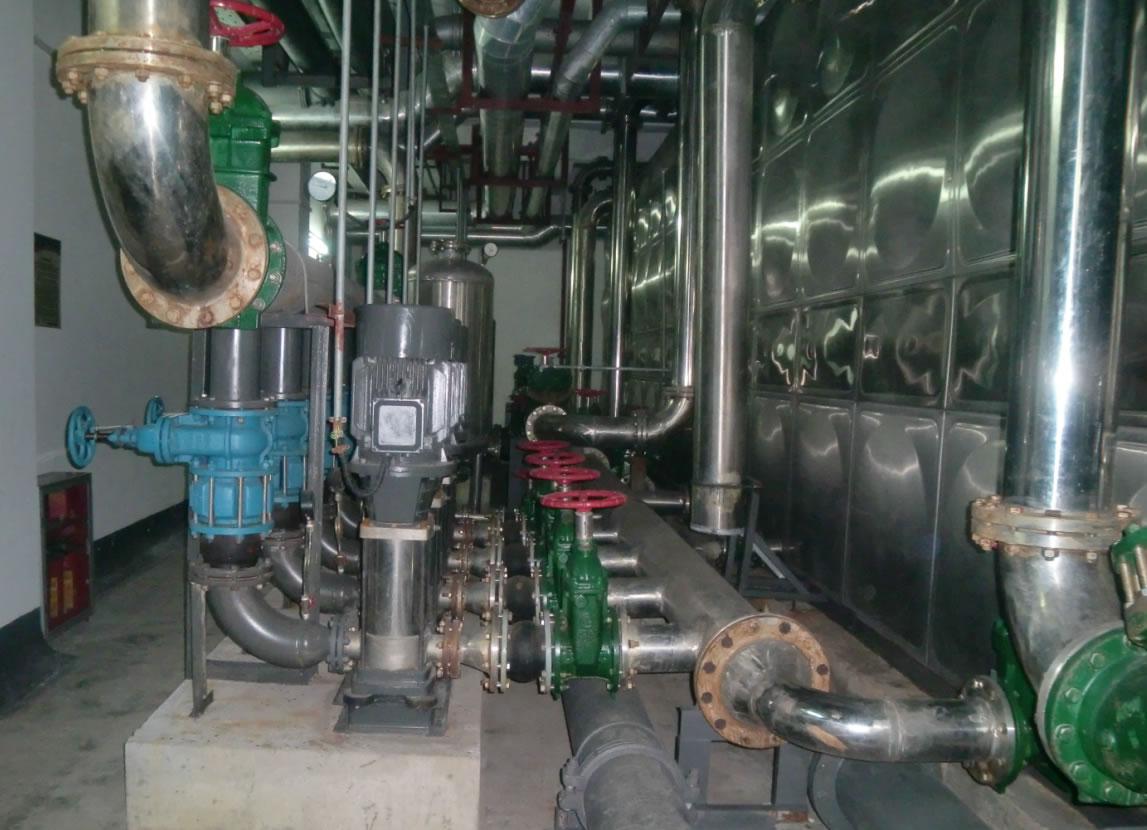
■ EN500/EN600 constant pressure water supply
EN500/EN600 constant pressure water supply technology is a new and mature technology developed by our company. It is widely used in the water supply industry because of its unique and excellent control performance. The special needs of water quality and safety have strict requirements for the constant pressure water supply, EN500/EN600 water supply scheme has advantages of stable water pressure, convenient operation, simple configuration, reliable operation, energy saving, and high degree of automation.
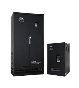
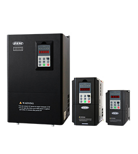
EN500/EN600 inbuilt with constant pressure water supply control algorithm, unique PID operation, pressure gage range setting, broken line protection, waterless protection.
■ EN500/EN600 constant pressure water supply(without using external water supply controller )
Working principle:1 piece of frequency inverter drive 1 piece of pump
Pipe network pressure < Setting pressure, frequency of frequency inverter increased, the pump speed increased, water supply increased, pipe network pressure rise.
Pipe network pressure = Setting pressure, frequency inverter output frequency remains unchanged, the pump speed unchanged, water supply unchanged, pipe network pressure remained stable.
Pipe network pressure > Setting pressure, frequency inverter output frequency is reduced (until sleep), pump speed is decelerated, water supply is reduced, and maintenance of pipe network water pressure stability.
Control process: The pressure sensor is installed on the water supply pipe and converts the pressure value to 0~10V voltage signal (or 4~20 mA current signal). The frequency inverter collects the feedback signal value of the pressure gauge in real time, and outputs the frequency value after the PID operation to regulate the speed of the water pump motor, and realizes the constant pressure of the water supply.
Hardware requirements:1 piece of pressure sensor, 1 piece of frequency inverter
Wiring method:The power line is connected with R, S, T; the motor line is connected with U, V, W; the start/stop switch wires are connected with X1 and COM; the pressure gage feedback signal line is connected with +10V, AI1 and GND. As below:

Parameters setting:
Function code |
Setting value |
Explanation |
F00.00 |
2 |
Senior list mode |
F00.23 |
1 |
P type |
F01.15 |
1 |
Terminal run command control |
F01.17 |
300 |
Acceleration time |
F01.18 |
300 |
Deceleration time |
F02.11 |
1 |
Free stop |
1. Basic parameter settings: acceleration and deceleration time, external terminal settings
Function code |
Setting value |
Explanation |
F12.00 |
1 |
One drive two mode |
F12.01 |
0.5( According to actual needs ) |
Target pressure setting |
F12.02 |
40( According to actual needs ) |
Sleep frequency |
F12.03 |
0.4( According to actual needs ) |
Awake pressure threshold |
F12.06 |
1( According to actual pressure gauge range ) |
Pressure gauge range |
2. PID parameter settings: F11 group PID function will be automatically effective after setting F12.00=1
3. (Optional) Double display of setting pressure and actual pressure:double display keyboard EN-LED2, LCD keyboard EN-LCD1/EN-LCD2 could display the set pressure and actual pressure simultaneously.
Function code |
Setting value |
Explanation |
F00.01 |
36 |
Setting pressure value display |
F00.25 |
37 |
Feedback pressure value display |
■ EN500/EN600 constant pressure water supply one drive two pumps(without using external water supply controller )
Working principle:1 piece of frequency inverter drive 2 pieces of pumps, power frequency and variable frequency switching working
Pipe network pressure < Setting pressure, No.1 pump work in variable frequency and speed up, and if it running frequency reach to upper limiting frequency but water pressure not sufficient, then No.1 pump switch to power frequency and No.2 pump start running in variable frequency.
Pipe network pressure = Setting pressure, The output frequency of the frequency inverter remains constant, the speed of the pump is constant, and the water supply is constant.
Pipe network pressure > Setting pressure, No.2 pump work in variable frequency and speed drop, and if it running frequency reach to lower limiting frequency but water pressure is still high, then No.1 pump disconnected with power frequency and leave the No.2 pump running in variable frequency.
Pipe network pressure < Setting pressure, the No.2 pump which formerly running in variable frequency will switch to power frequency, No.1 pump start running in variable frequency. Go round and begin again.
Hardware requirements:1 piece of pressure sensor, 1 piece of frequency inverter, 4 pieces of auxiliary relays, 4 pieces of AC contactor, 2 pieces of thermal relays
Control process:The pressure sensor is installed on the water supply pipe and converts the pressure value to 0~10V voltage signal (or 4~20 mA current signal). The frequency inverter collects the feedback signal value of the pressure gauge in real time, and outputs the frequency value after the PID operation to regulate the speed of the water pump motor. The pump will be switched to power frequency when this pump cannot supply sufficient water, then frequency inverter will start the other pump. Two pumps work in duty-cycle operation between power frequency and variable frequency to realize constant pressure water supply.
Wiring method:The power line is connected with R, S, T; the motor line is connected with U, V, W; the start/stop switch wires are connected with X1 and COM; the pressure gage feedback signal line is connected with +10V, AI1 and GND. The auxiliary relays KA0, KA1, KA2, KA3 are connected to frequency inverter terminals Y1, Y2, Y3, Y4 respectively. AC contactor KM0, KM1, KM2, KM3, are connected to No.1 pump variable frequency, No.1 pump power frequency, No.2 pump variable frequency, No.2 pump power frequency. As below:

?
Parameters setting:
Function code |
Setting value |
Explanation |
F00.00 |
2 |
Senior list mode |
F00.23 |
1 |
P type |
F01.15 |
1 |
Terminal run command control |
F01.17 |
300 |
Acceleration time |
F01.18 |
300 |
Deceleration time |
F02.11 |
1 |
Free stop |
1.Basic parameter settings: acceleration and deceleration time, external terminal settings
2. PID parameter settings: F11 group PID function will be automatically effective after setting F12.00=1
Function code |
Setting value |
Explanation |
F12.00 |
1 |
One drive two mode |
F12.01 |
0.5( According to actual needs ) |
Target pressure setting |
F12.02 |
40( According to actual needs ) |
Sleep frequency |
F12.03 |
0.4( According to actual needs ) |
Awake pressure threshold |
F12.06 |
1( According to actual pressure gauge range ) |
Pressure gauge range |
F09.00 |
37 |
No. 1 pump variable frequency |
F09.01 |
38 |
No. 1 pump power frequency |
F09.02 |
39 |
No. 2 pump variable frequency |
F09.03 |
40 |
No. 2 pump power frequency |
3. (Optional) Double display of setting pressure and actual pressure:double display keyboard EN-LED2, LCD keyboard EN-LCD1/EN-LCD2 could display the set pressure and actual pressure simultaneously.
Function code |
Setting value |
Explanation |
F00.01 |
36 |
Setting pressure value display |
F00.25 |
37 |
Feedback pressure value display |
■Matters needing attention:
1、 Deep well pumps (or deep submersible pumps) need to use G type;
2、 When no people is on duty, please set the pressure gauge broken line detection to prevent water pipe burst which caused by pressure gauge fault or broken line;
3、 If there is no water, please set up the under load protection to prevent the pump from idling and cause damage.
?


 Mail
Mail Online Service